 SIXCNC.COM
CNC machine parts
HMI & PLC
Electrical devices
Posts
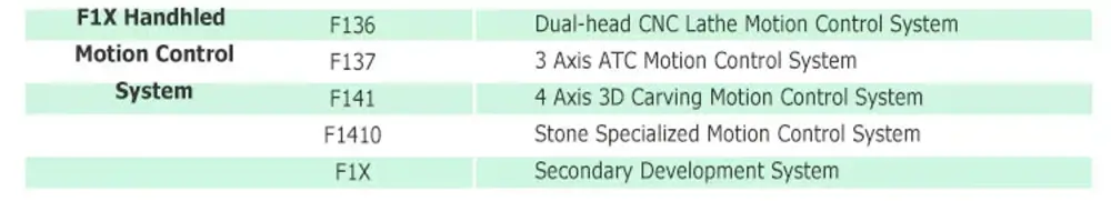
CNC controller
type
status
date
slug
summary
tags
category
icon
password
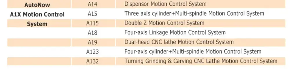
📙Model & price
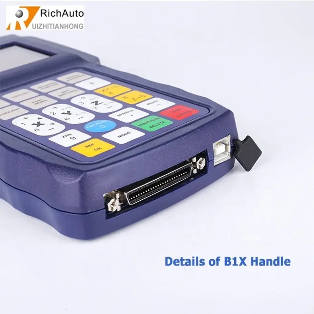
1.DSP controller
📄RichAuto DSP controller
- DSP A11
- DSP 0501
- DSP A12
- DSP A15
- DSP A18
- DSP B15
- DSP B18
- DSP B51
- DSP B57
- DSP B58
- DSP F131
- DSP F135
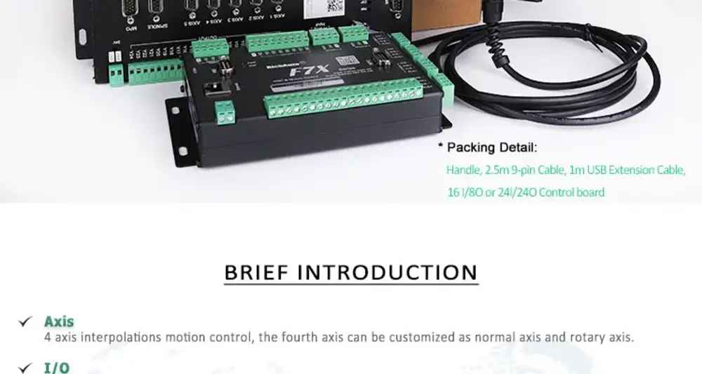
- DSP F141
- DSP F1410
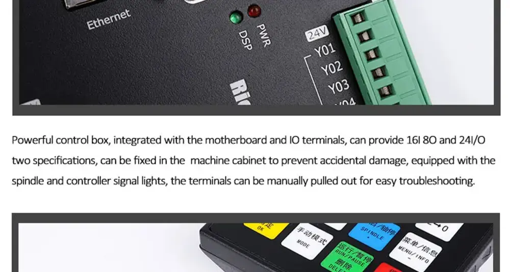
📙Product description
1.DSP controller
📄RichAuto DSP controller
[1]DSP A11
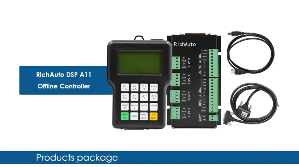
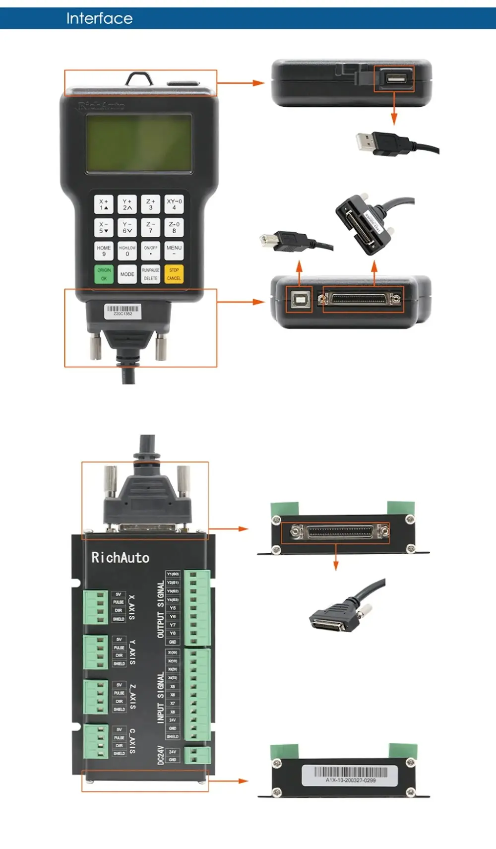
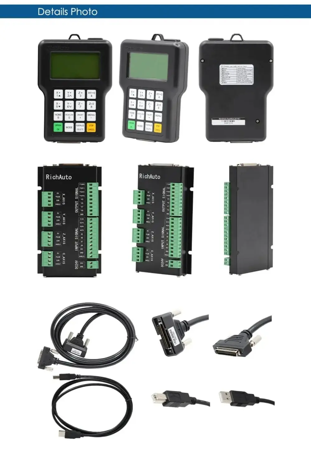
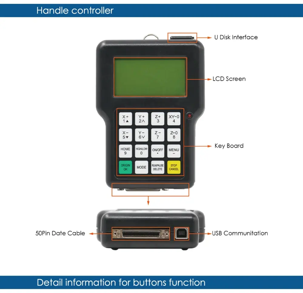
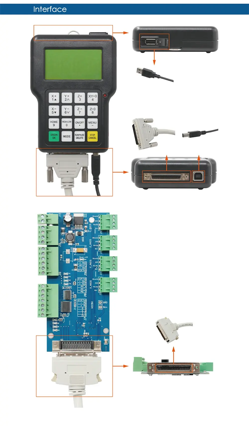
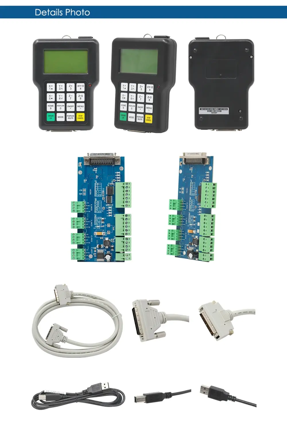
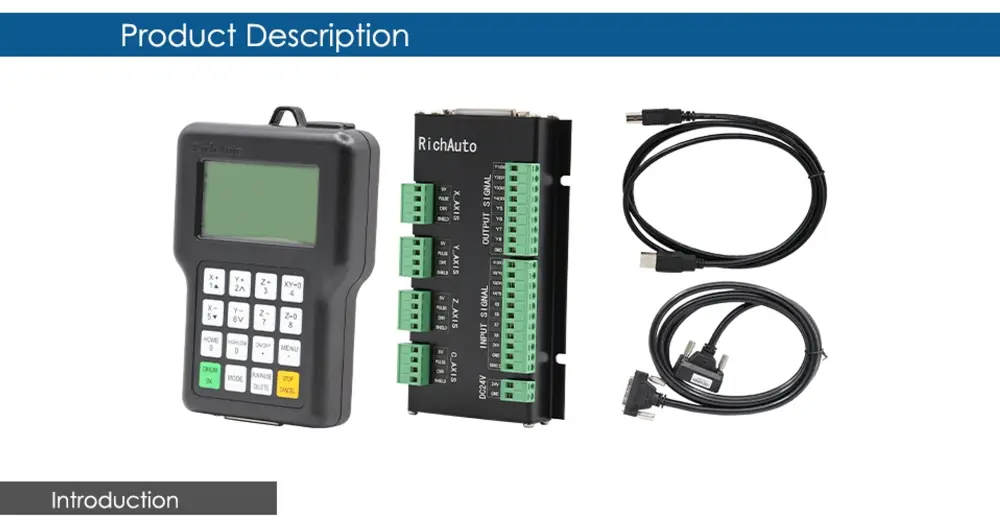
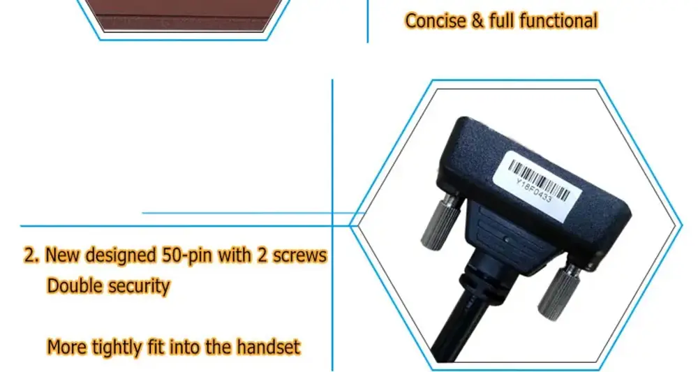
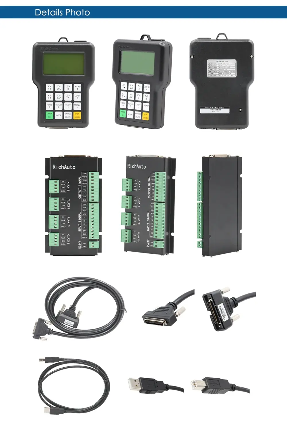
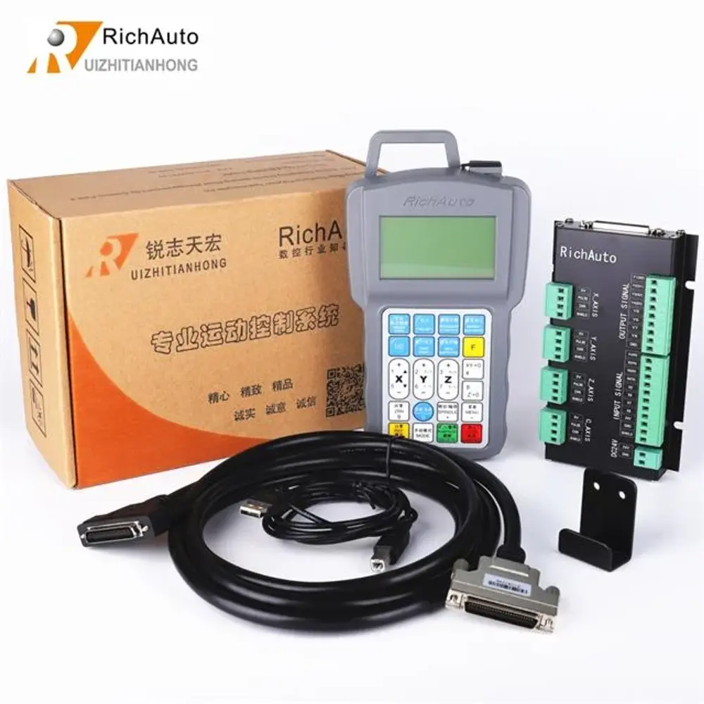
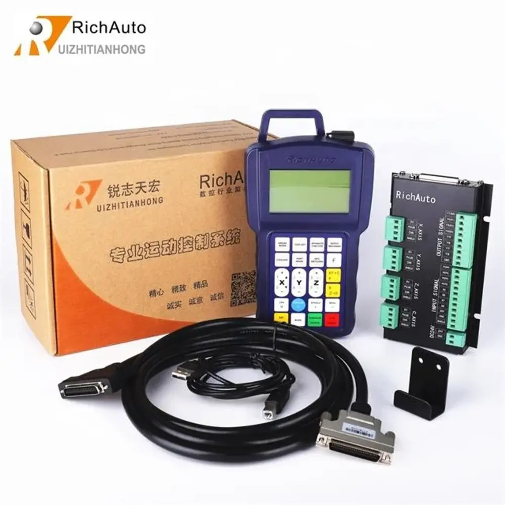
1pcs -- DSP Handle Controller - A11 (Three-axis Linkage Motion Control System)
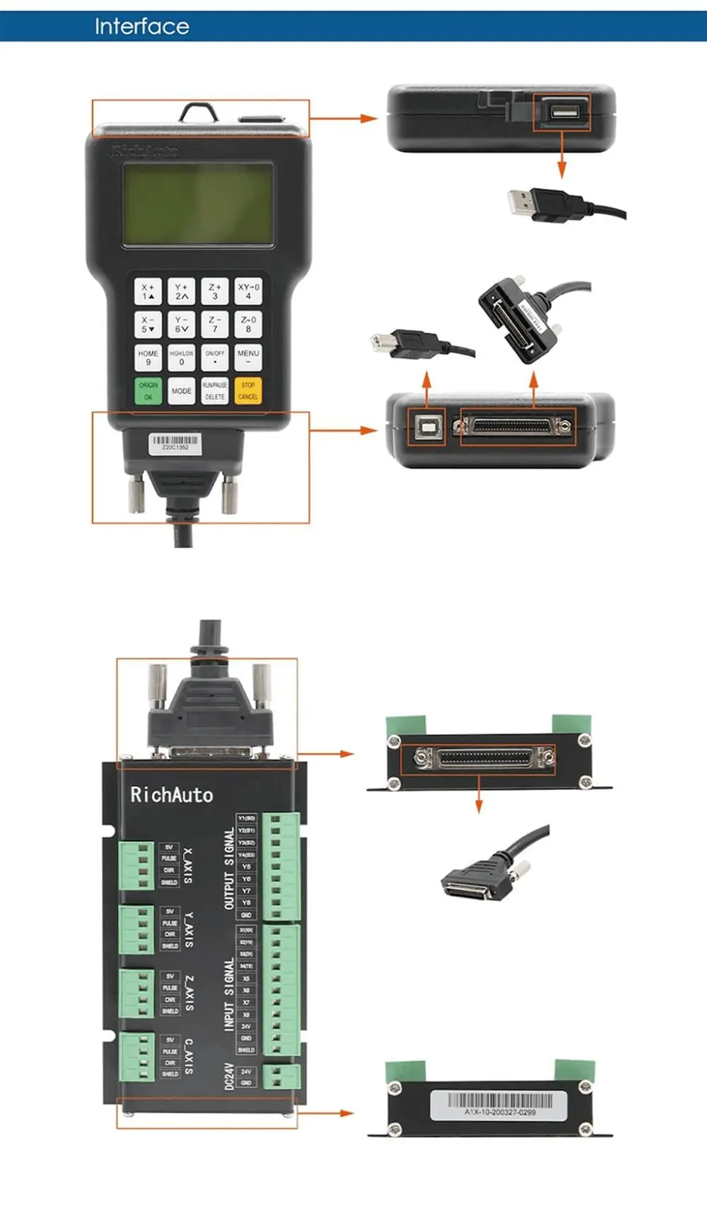
1pcs -- 50 pin Data Cable
1pcs -- USB Cable
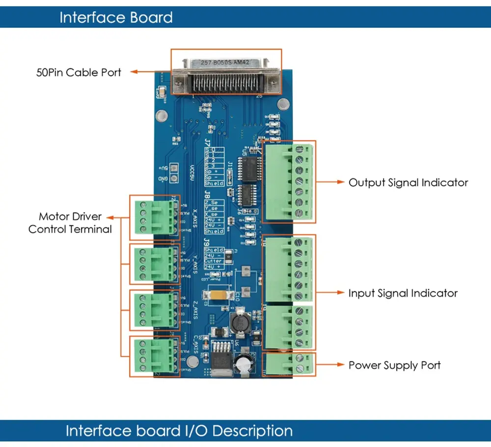
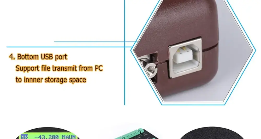
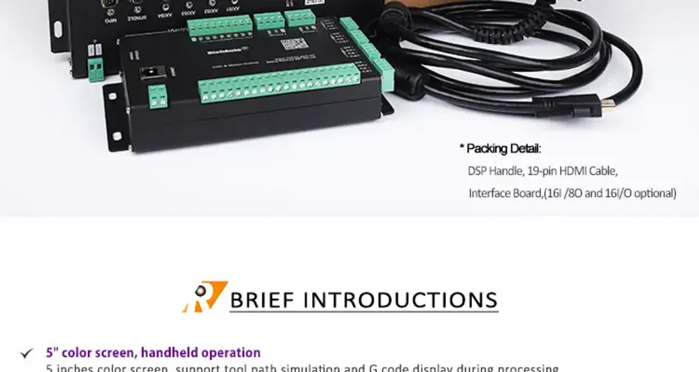
1pcs -- I/O Wiring Board

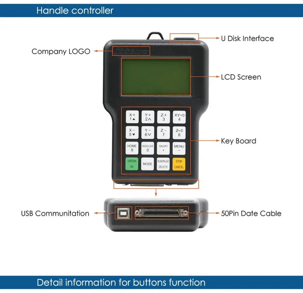
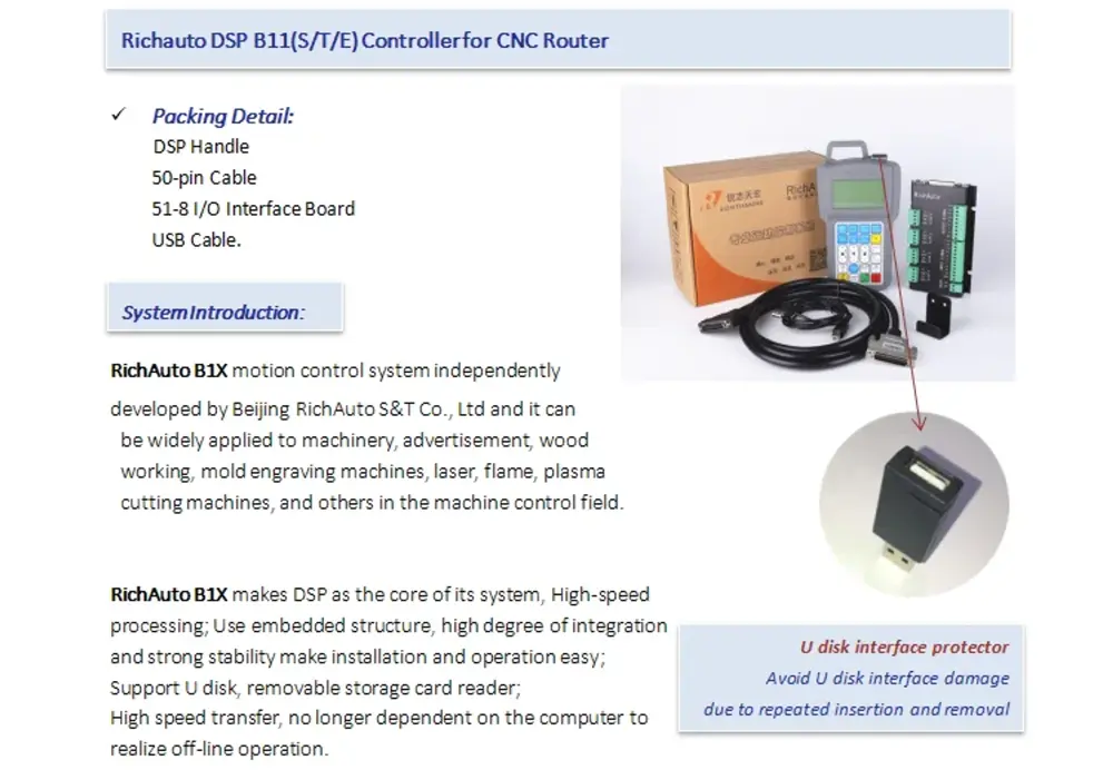
RichAuto is a CNC motion control system, that can be widely applied to machinery, advertisement, woodworking, mold engraving machines, laser, flame, plasma cutting machines, and so on in the machine control field.
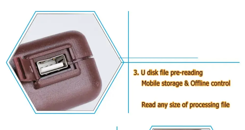
RichAuto makes DSP as the core control system, high-speed processing operation is the microcontroller, PLC systems can’t match; Use embedded structure, high degree of integration, strong stability, easy to install and operation; U disk support, removable storage card reader, with USB Interface, high-speed transfer, plug and play the full realization of all work offline.
Type | Data |
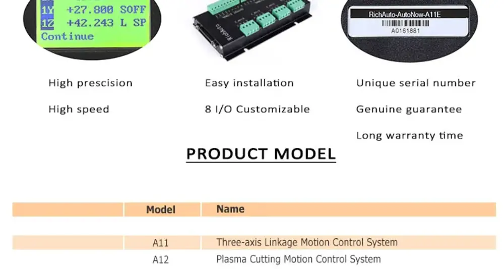
Product Model | RichAuto---A11E |
CPU | DSP |
Internal Memory | 512MB |
Display Screen | 128*64 Monochrome LCD |
Communication Port | U disk, USB cable |
Controller Axis Number | 3 axes |
Control Signal | Different signal |
Drive System | Stepper motor/Servo motor |
Min. Input Unit | 0.001mm |
No Volt Protection | Support |
Breakpoint Processing Function | 8 |
External Power Supply Voltage | 24VDC |
Manual Mode | Continuous, point move, distance |
Interpolation Way | line, arc |
Soft/Hard Limit | support |
Max. Pulse Frequency | 1M/S |
Password Protection | support |
Support Language | English |
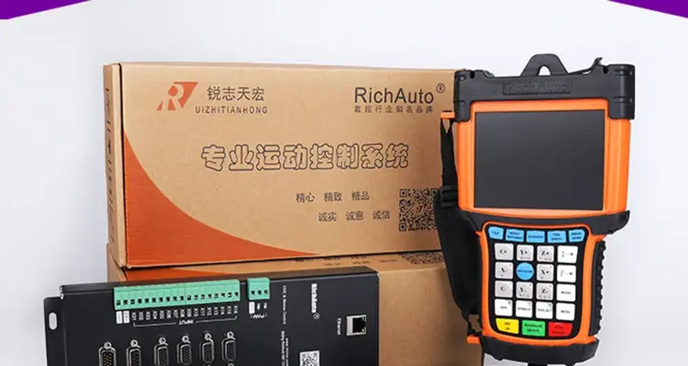
Standard Configuration | (1) DSP Handle,(1) 50 core cable, (1)USB cable,(1)8 I/O Wiring board |
Pay Attention:This is the original RichAuto A11 E, more stable than the copy type. You also can update the software by yourself. copy type can't do it.

Feature:
- High-performance core processing CPU: The eight nuclear processing CPUs, have faster calculation, and stronger processing ability.
- Simple handle structure with buttons controls: 16 buttons operation mode, comfortable hand-held end, easy to learn, easy to use, simple and quick.
- Multiple data transmission, large storage capacity support: Completely off-line operation and support a variety of mobile storage transmission methods; 512MB internal memory, can read large capacity storage mobile devices.
- Intelligent reading processing documents function: AutoNow series products are smart in proofreading the processing documents, to new processing files, only reading before the first time operation. In the process of reading, it can also skip checking according to customers’ demands which saves the users’ valuable time to a great degree.
- Intelligent memory function: supports power loss and breakpoint processing; not only storage of the process position but also the memory of the file name, ensuring users continue processing from breakpoint quickly & accurately.
- Two kinds of processing mode choices: high precision mode and ensure machining precision and quality high-speed mode, which ensure the process efficiency, saving processing time.
- Security checking & alarm: Add security warning system and abnormal reminder functions, such as back to zero abnormal shaft mark, distance mode mobile safety tips, and processing beyond the function such as display, greatly guarantee the accuracy and consistency of processing.
- More perfect encryption functions: Hardware encryption, set parameters encryption, running time of encryption and the internal important processing file encryption, and other functions, the modification, prevent delete, prevent copying, and to ensure the customers’ technical information and assets safe.
- Anti-jamming performance is greatly increased: Through some CE tests, anti-jamming is greatly improved.
- Department stronger: AutoNow-based version 8 series of 8 out into the support I/O mouth custom editing functions, the user can completely according to their own needs editing and defined, and may expand to 32 input 32 output; Based on 8 nuclear processing CPU, but also for secondary development, for the customer equipments of the special function, special purpose to add, meet the needs of different industries, with period is short, the cost is low, the secrecy id good wait for a characteristic.
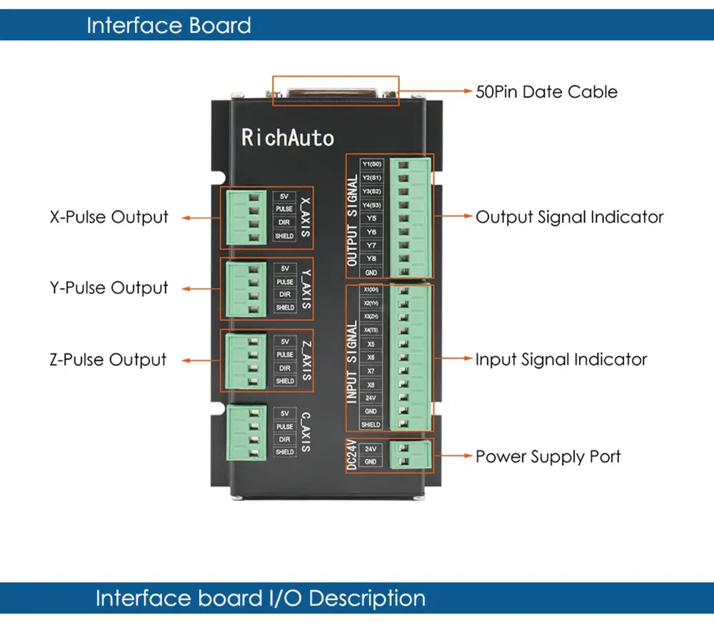
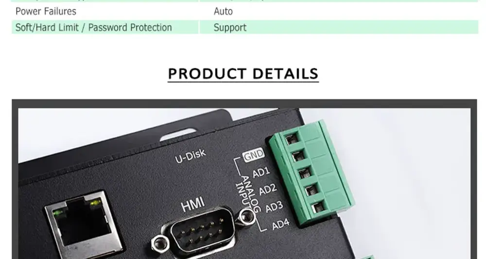
Port definition | Port label | Pin Definition | Pin functions
and parameters | Notes |
DC24V | 24V+ | System main power supply port | System main power supply terminal, and interface board give DC 5V for the system. | Power area:
DC10V~DC24V/ 3A~40V |
ㅤ | 24V- | ㅤ | ㅤ | ㅤ |
X-AXIS | 5V | 5V signal output por | X-axis drive common anode power supply terminal 5V output | Do not impose voltage on this pin |
ㅤ | PULSE | Pulse signal output port | X-axis drive pulse signal output port, the output voltage ≧ 3V drive current≦ 8mA | ㅤ |
ㅤ | DIR | direction signal
output port | X-axis direction of the drive signal output port output voltage ≧ 3V drive current≦ 8mA | ㅤ |
ㅤ | SHIELD | Shield
connection port | X-axis drive signal output voltage line terminal shield | Do not impose voltage on this pin |
Y-AXIS | 5V | 5V signal output port | Y-axis drive common anode power supply terminal 5V output | Do not impose voltage on this pin |
ㅤ | PULSE | Pulse signal output port | Y-axis drive pulse signal output port, the output voltage ≧ 3V drive current≦ 8mA | ㅤ |
ㅤ | DIR | direction signal
output port | Y-axis direction of the drive signal output port output voltage ≧ 3V drive current≦ 8mA | ㅤ |
ㅤ | SHIELD | Shield
Connection port | Y-axis drive signal output voltage line terminal shield | Do not impose voltage on this pin |
Z-AXIS | 5V | 5V signal output port | Z-axis drive common anode power supply terminal 5V output | Do not impose voltage on this pin |
ㅤ | PULSE | Pulse signal output port | Z-axis drive pulse signal output port, the output voltage ≧ 3V drive current≦ 8mA | ㅤ |
ㅤ | DIR | direction signal
output port | Z-axis direction of the drive signal output port output voltage ≧ 3V drive current≦ 8mA | ㅤ |
ㅤ | SHIELD | Shield
connection port | Z-axis drive signal output voltage line terminal shield | Do not impose voltage on this pin |
Port definition | Port label | Pin Definition | Pin functions
and parameters | Notes |
OUTPUT
SIGNAL | Y01 | Y1(S0): Spindle ON/OFF | Connect to FWD of inverter | Output Low-level signal |
ㅤ | Y02 | Y2(S1):speed 1 | Connect to the inverter to control the speed | ㅤ |
ㅤ | Y03 | Y3(S2):speed 2 | Connect to the inverter to control the speed | ㅤ |
ㅤ | Y04 | Y4(S3):speed 3 | Connect to the inverter to control the speed | ㅤ |
ㅤ | Y05 | Y5(S4):Alarm LED | Light when there is something wrong with the system | ㅤ |
ㅤ | Y06 | Y6(S5):Work LED | Light when the system works | ㅤ |
ㅤ | Y07 | Y7(S6):definable | user-defined signal | ㅤ |
ㅤ | Y08 | Y8(S7):definable | user-defined signal | ㅤ |
ㅤ | GND | GND: Output GND | ㅤ | GND connects to this terminal in the control inverter speed mode |
INPUT
SIGNAL | X01 | X1:X_se:X origin sensor Signal Input | X origin sensor signal input terminal | Input low-level signals |
ㅤ | X02 | X2:Y_se: Y origin sensor
Signal Input | Y origin sensor signal input terminal | ㅤ |
ㅤ | X03 | X3:Z_se:Z origin sensor
Signal Input | Z origin sensor signal input terminal | ㅤ |
ㅤ | X04 | X4:CutterTool-setting sensor signal input | Tool-setting sensor signal input terminal | ㅤ |
ㅤ | X05 | X5:Driver alarm signal input | Driver alarm signal input terminal | ㅤ |
ㅤ | X06 | X6:Hard limit signal input | Hard Limit signal input terminal | ㅤ |
ㅤ | X07 | X7:E-stop signal input | E-stop signal input terminal | ㅤ |
ㅤ | X08 | X8:Definable signal | Definable signal input terminal | ㅤ |
ㅤ | 24V | 24V+:Sensor power input | X、Y、Z sensor isolate circuit power supply positive input terminal | Sensor isolate circuit supply voltage range DC10V~DC24V |
ㅤ | GND | GND: GDN input | X、Y、Z sensors isolate the circuit power supply negative input terminal | ㅤ |
ㅤ | SHIELD | Shield: Shield input | Sensor signal cable shield input terminal | Do not use this port as a negative use of the sensor isolation circuit power |
Advantage:
- New three-axis motion mode, realizing comprehensive control.
- Support xyz driver, spindle frequency converter processing error alarm prompt function.
- Large storage space, strong U disk compatibility, fast reading speed, and more reliable U disk processing.
- Intelligent file checking function.
- With parameter backup and recovery functions, it effectively prevents the loss of important parameters.
- More anti-interference, passing multiple ce tests.
- Intelligent processing and memory function, supporting breakpoint and power failure function.
- The I/O interface can be customized and edited to provide users with a wide range of development platforms.
[2]DSP 0501
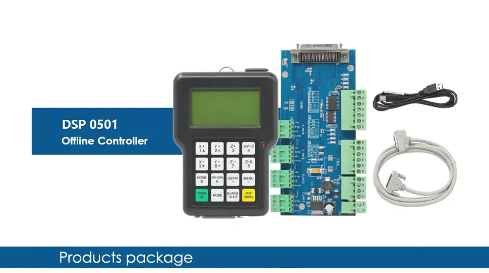
1pcs & DSP Handle
1pcs & 50 core cable
1pcs & USB cable
1pcs & I/O wiring board
Introduction
- Color handheld motion control system using TI's DSP American movement dedicated control chip, and with independent intellectual property.
- The right to exercise the core axis hardware is carefully designed, and a separate system for computer work offline.
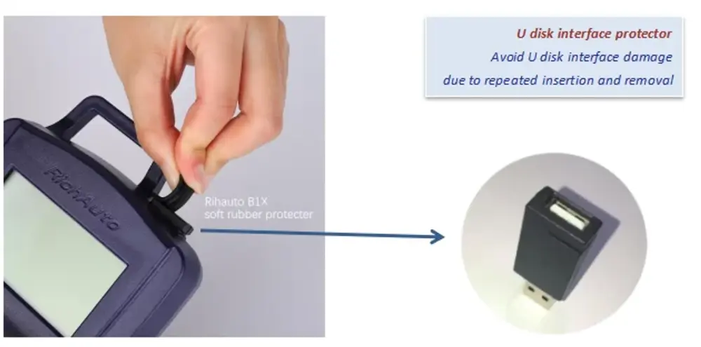
- Among the work without computer intervention. Internal configuration of large-capacity flash memory and can be read external large-capacity memory.
- The unique design ensures maximum compatibility with external USB storage devices, U disk recognition rate, and read.
- Failure rate. Cheap and reliable interface design makes system maintenance simple and easy maintenance. Since it is reliable.
- I diagnostic functions, and fast troubleshooting. Multi-language switching, localization fast and easy to spread. Convenient Jane.
- Single firmware upgrade mechanism to remotely upgrade functionality.
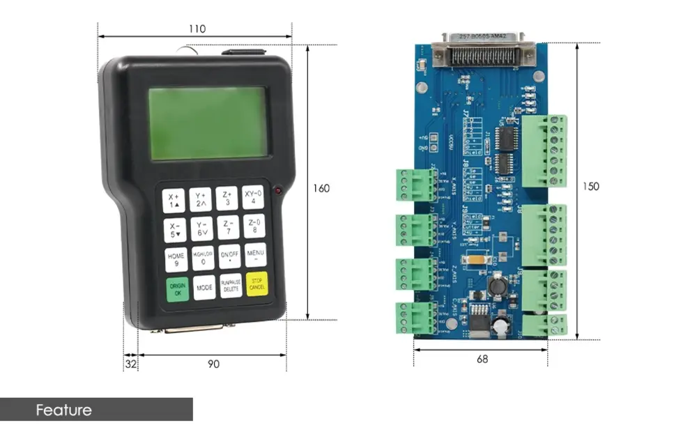
Type | Data |
Product Model | DSP 0501 |
Processor | 160M DSP |
File Memorizer | 128M memorizer inside, it supports files of any size because of adopting mobile memorize technology |
Display | LCD with 128 dot*64 dot |
Communication Terminals | USB terminal and U Disk |
File Format | G code, PLT files (optional) |
Axes | 3 axes |
Help Function | Useful help information and guide |
Languages | Chinese, English, Russian, France, and Japanese(optional or customized) |
Operating Interface | Friendly Buttons and Menu Drive |
Drive System | Step Motors |
Interpolation function | linear, curve |
Cutter Adjusting function | Yes |
Spindle Control Function | Yes |
System Data Inspect Function | Yes |
Processing Data Inspect Function | Yes |
Processing Position Adjusting Function | Yes |
Multi Working Coordinates | It has 9 working coordinates |
Stop Point Reprocessing Function | Yes |
Copy Processing Function | Yes |
Data protection when power off | Yes |
Working Temperature | 0C to +70C |
Humidity | <90 no dew no frost |
Outer Voltage | 5 V |
Consumptions | 2 W |
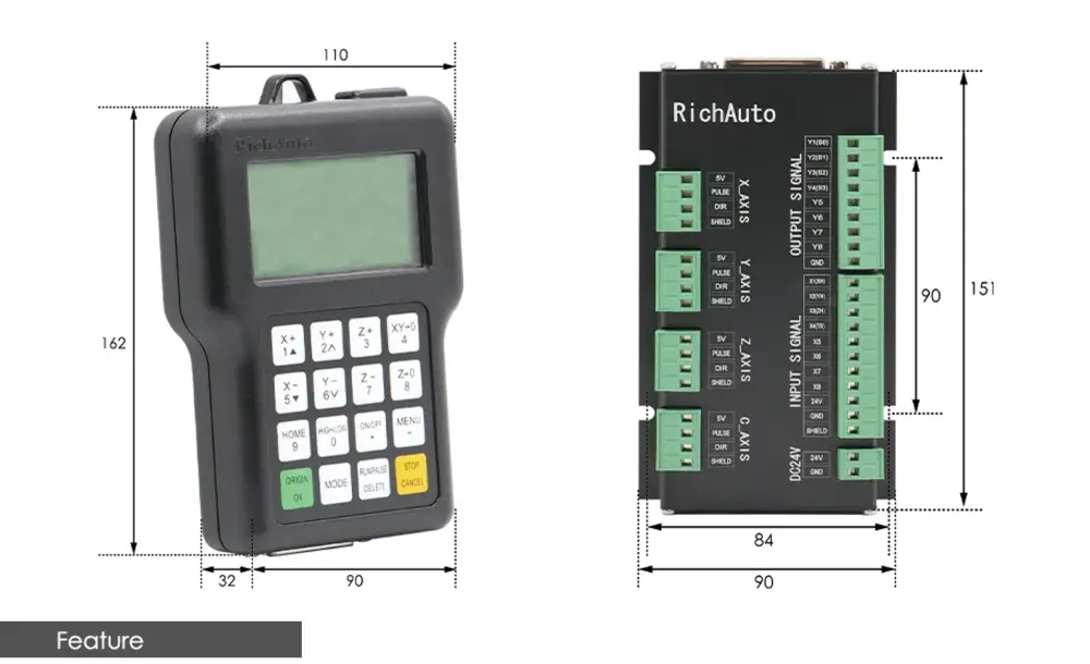
Dimensions(mm) | 156*110*38 |
Feature
- Embedded systems.
- USB storage devices read.
- Multiple formats of G code and PLT (HPGL) files read.
- G code writing error checking.
- Preflight processing code.
- Parameter setting safety value protection.
- Machine safety size restrictions.
- Self-diagnostic system.

Port definition | Port label | Pin Definition | Pin functions | Notes |
DC24V | 24V+ | System main power supply port | System's main power supply terminal, and interface board give DC 5V for the system. | Power area: |
ㅤ | 24V- | ㅤ | ㅤ | ㅤ |
X-AXIS | 5V | 5V signal output port | X-axis drive common anode power supply terminal 5V output | Do not impose voltage on this pin |
ㅤ | PULSE | Pulse signal output port | X-axis drive pulse signal output port, the output voltage ≧ 3V drive current≦ 8mA | ㅤ |
ㅤ | DIR | direction signal | X-axis direction of the drive signal output port output voltage ≧ 3V drive current≦ 8mA | ㅤ |
ㅤ | SHIELD | Shield | X-axis drive signal output voltage line terminal shield | Do not impose voltage on this pin |
Y-AXIS | 5V | 5V signal output port | Y-axis drive common anode power supply terminal 5V output | Do not impose voltage on this pin |
ㅤ | PULSE | Pulse signal output port | Y-axis drive pulse signal output port, the output voltage ≧ 3V drive current≦ 8mA | ㅤ |
ㅤ | DIR | direction signal | Y-axis direction of the drive signal output port output voltage ≧ 3V drive current≦ 8mA | ㅤ |
ㅤ | SHIELD | Shield | Y-axis drive signal output voltage line terminal shield | Do not impose voltage on this pin |
Z-AXIS | 5V | 5V signal output port | Z-axis drive common anode power supply terminal 5V output | Do not impose voltage on this pin |
ㅤ | PULSE | Pulse signal output port | Z-axis drive pulse signal output port, the output voltage ≧ 3V drive current≦ 8mA | ㅤ |
ㅤ | DIR | direction signal | Z-axis direction of the drive signal output port output voltage ≧ 3V drive current≦ 8mA | ㅤ |
ㅤ | SHIELD | Shield | Z-axis drive signal output voltage line terminal shield | Do not impose voltage on this pin |
C-AXIS | 5V | 5V signal output por | C-axis drive common anode power supply terminal 5V output | Do not impose voltage on this pin |
ㅤ | PULSE | Pulse signal output port | C-axis drive pulse signal output port, the output voltage ≧ 3V drive current≦ 8mA | ㅤ |
ㅤ | DIR | direction signal output port | The c-axis direction of the drive signal output port output voltage ≧ 3V drive current≦ 8mA | ㅤ |
ㅤ | SHIELD | Shield connection port | C-axis drive signal output voltage line terminal shield | Do not impose voltage on this pin |
and parametersDC10V~DC24V/ 3A~40Voutput portconnection portoutput portConnection portoutput portconnection port
Hardware Resources:
- TI DSP movement dedicated processor
- Hardware core axis movement
- USB host interface (external memory read)
- USB (maintenance system) from the interface
- 8 inputs and outputs (expandable to 64 into 64)
- D / A output (optional)
[3]DSP A12
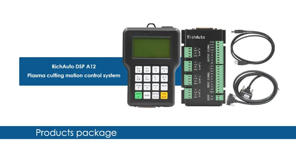
1pcs & DSP Handle Controller (A12 - Plasma Cutting Motion Control System)
1pcs & 50 pin Data Cable
1pcs & USB Cable
1pcs & I/O Wiring Board
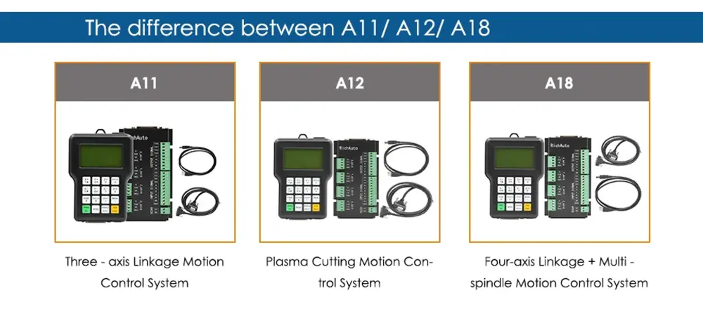
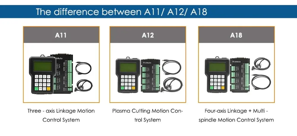
Product A11 (Three-axis Linkage Motion Control System)
Product A12 (Plasma Cutting Motion Control System)
Product A18 (Four-axis Linkage + Multi-spindle Motion Control System)
RichAuto is a CNC motion control system, that can be widely applied to machinery, advertisement, woodworking, mold engraving machines, laser, flame, plasma cutting machines, and so on in the machine control field.
RichAuto makes DSP as the core control system, high-speed processing operation is the microcontroller, PLC systems can’t match; Use embedded structure, high degree of integration, strong stability, easy to install and operation; U disk support, removable storage card reader, with USB Interface, high-speed transfer, plug and play the full realization of all work offline.
Type | Data |
Product Model | RichAuto---A12 |
CPU | DSP |
Internal Memory | 512MB |
Display Screen | 128*64 Monochrome LCD |
Communication Port | U disk, USB cable |
Controller Axis Number | 2-3 axes |
Control Signal | Different signal |
Drive System | Stepper motor/Servo motor |
Min. Input Unit | 0.001mm |
No Volt Protection | Support |
Breakpoint Processing Function | Support |
External Power Supply Voltage | 24VDC |
Manual Mode | Continuous, point move, distance |
Interpolation Way | line, arc, spline |
Soft/Hard Limit | support |
Max. Pulse Frequency | 1M/S |
Password Protection | support |
Support Language | English |
Standard Configuration | (1) DSP Handle,(1) 50 core cable, (1)USB cable,(1)8 I/O Wiring board |
Pay Attention: This is the original RichAuto A12, more stable than copy type.
You also can update the software by yourself. copy type can't do it.
Feature
- Adopting position control mode, support 3-ais and 4-axis linkage motion control, double Y drive.
- Standard with 8 Input/Output interface board.
- Support various processing formats, such as G code, PLT, bitmap DXF, etc.
- Intelligent memory function, support power failure protection, and breakpoint processing function.
- Support portable storage mode function.
- Multi-coordinate memory function. Provide 9 work coordinates system, the user can switch among the 9 coordinates, each coordinate system can save a process origin information.
- Support adjusting spindle frequency during processing. The spindle frequency from 0 to maximum frequency is divided into 8 gears, 1-8 gears can be processed directly and adjusted up and down without suspend processing.
- Support adjusting speed ratio during processing. Users can adjust the speed ratio from 0.1-1, ascending or descending per 0.1 numerical.
- Simple manual operation mode. Including “Continue, Step, Dist”, the manual operation becomes more simple and convenient.10. Support M, F code and other expanded codes, special codes can be customized according to the actual request.
- Built-in 512 Mb memory. Communication by USB interface.
- Unique handheld form to realize holding by one hand. A liquid crystal display and 16 buttons make operating intuitive and flexible. No longer dependent on the computer to realize off-line operation.
- Self-test function, the system supports I/O signal detection capabilities to make remote maintenance easy.
- Support multiple languages, such as Spanish, French, Arabic, etc.
- The system supports automatic dynamic upgrading that makes remote operation and remote maintenance convenient.
Port definition | Port label | Pin Definition | Pin functions
and parameters | Notes |
DC24V | 24V+ | System main power supply port | The system's main power supply terminal and interface board give DC 5V for the system. | Power area:
DC10V~DC24V/ 3A~40V |
ㅤ | 24V- | ㅤ | ㅤ | ㅤ |
X-AXIS | 5V | 5V signal output por | X-axis drive common anode power supply terminal 5V output | Do not impose voltage on this pin |
ㅤ | PULSE | Pulse signal output port | X-axis drive pulse signal output port, the output voltage ≧ 3V drive current≦ 8mA | ㅤ |
ㅤ | DIR | direction signal
output port | X-axis direction of the drive signal output port output voltage ≧ 3V drive current≦ 8mA | ㅤ |
ㅤ | SHIELD | Shield
connection port | X-axis drive signal output voltage line terminal shield | Do not impose voltage on this pin |
Y-AXIS | 5V | 5V signal output port | Y-axis drive common anode power supply terminal 5V output | Do not impose voltage on this pin |
ㅤ | PULSE | Pulse signal output port | Y-axis drive pulse signal output port, the output voltage ≧ 3V drive current≦ 8mA | ㅤ |
ㅤ | DIR | direction signal
output port | Y-axis direction of the drive signal output port output voltage ≧ 3V drive current≦ 8mA | ㅤ |
ㅤ | SHIELD | Shield
Connection port | Y-axis drive signal output voltage line terminal shield | Do not impose voltage on this pin |
Z-AXIS | 5V | 5V signal output port | Z-axis drive common anode power supply terminal 5V output | Do not impose voltage on this pin |
ㅤ | PULSE | Pulse signal output port | Z-axis drive pulse signal output port, the output voltage ≧ 3V drive current≦ 8mA | ㅤ |
ㅤ | DIR | direction signal
output port | Z-axis direction of the drive signal output port output voltage ≧ 3V drive current≦ 8mA | ㅤ |
ㅤ | SHIELD | Shield
connection port | Z-axis drive signal output voltage line terminal shield | Do not impose voltage on this pin |
Port definition | Port label | Pin Definition | Pin functions
and parameters | Notes |
OUTPUT
SIGNAL | Y01 | Y1(S0): Spindle ON/OFF | Connect to FWD of inverter | Output Low-level signal |
ㅤ | Y02 | Y2(S1):speed 1 | Connect to the inverter to control the speed | ㅤ |
ㅤ | Y03 | Y3(S2):speed 2 | Connect to the inverter to control the speed | ㅤ |
ㅤ | Y04 | Y4(S3):speed 3 | Connect to the inverter to control the speed | ㅤ |
ㅤ | Y05 | Y5(S4):Alarm LED | Light when there is something wrong with the system | ㅤ |
ㅤ | Y06 | Y6(S5):Work LED | Light when the system works | ㅤ |
ㅤ | Y07 | Y7(S6):definable | user-defined signal | ㅤ |
ㅤ | Y08 | Y8(S7):definable | user-defined signal | ㅤ |
ㅤ | GND | GND: Output GND | ㅤ | GND connects to this terminal in the control inverter speed mode |
INPUT
SIGNAL | X01 | X1:X_se:X origin sensor Signal Input | X origin sensor signal input terminal | Input low-level signals |
ㅤ | X02 | X2:Y_se:Y origin sensor
Signal Input | Y origin sensor signal input terminal | ㅤ |
ㅤ | X03 | X3:Z_se:Z origin sensor
Signal Input | Z origin sensor signal input terminal | ㅤ |
ㅤ | X04 | X4:CutterTool-setting sensor signal input | Tool-setting sensor signal input terminal | ㅤ |
ㅤ | X05 | X5:Driver alarm signal input | Driver alarm signal input terminal | ㅤ |
ㅤ | X06 | X6:Hard limit signal input | Hard Limit signal input terminal | ㅤ |
ㅤ | X07 | X7:E-stop signal input | E-stop signal input terminal | ㅤ |
ㅤ | X08 | X8:Definable signal | Definable signal input terminal | ㅤ |
ㅤ | 24V | 24V+:Sensor power input | X、Y、Z sensor isolate circuit power supply positive input terminal | Sensor isolate circuit supply voltage range DC10V~DC24V |
ㅤ | GND | GND:GDN input | X、Y、Z sensors isolate the circuit power supply negative input terminal | ㅤ |
ㅤ | SHIELD | Shield: Shield input | Sensor signal cable shield input terminal | Do not use this port as a negative use of the sensor isolation circuit power |
Advantage
- High-speed 8-core CPU with strong processing power and fast computing speed.
- U disk compatibility is strong. Fast reading speed, more reliable U disk processing.
- With parameter backup and recovery functions, it effectively prevents the loss of important parameters.
- More anti-interference, passing multiple CE tests.
- The output port can be customized for control, such as external equipment such as a cylinder, arc voltage regulator, etc.
- The system provides the test function of processing the workpiece frame, which makes it easier to place the work materials.
- New calculation processing mode, effectively preventing corner burning in plasma cutting.

[4]DSP A15
Type | Data |
Product model | RichAuto A15 |
CPU | DSP |
Internal Memory | 512MB |
Display Screen | 128*64 Monochrome LCD |
Communication Port | U disk, USB cable |
Support Language | Simple Chinese/Traditional Chinese, English, other languages |
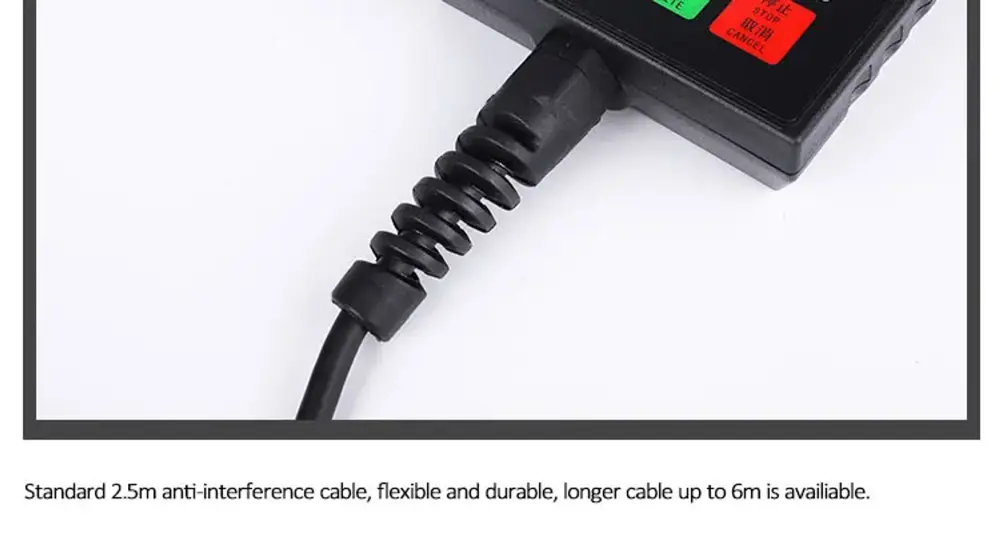
Standard Configuration | (1) DSP Handle;(1) 50 Core Cable (1)USB Cable; (1)8 I/O Wiring board;(1) Data CD |

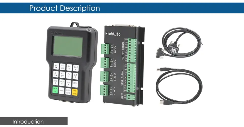
[5]DSP A18
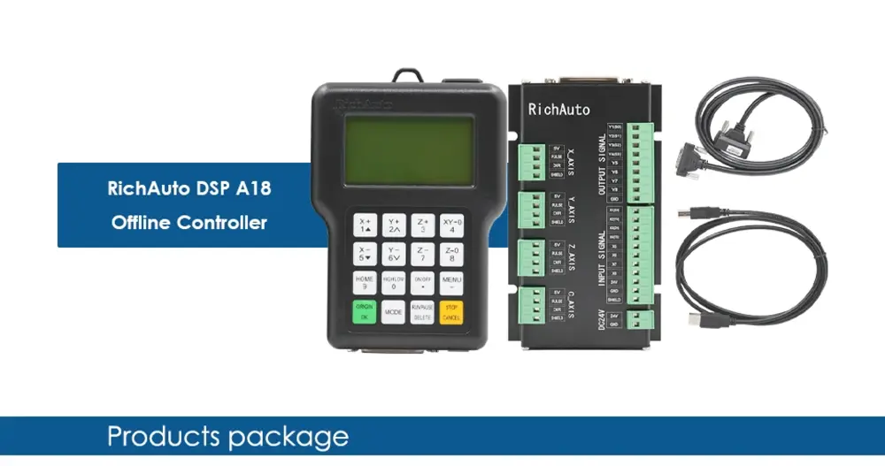
1pcs & DSP Handle - A18 (Four-axis Linkage + Multi-spindle Motion Control System)
1pcs & 50 core cable
1pcs & USB cable
1pcs & I/O wiring board

Product A11 (Three-axis Linkage Motion Control System)
Product A12 (Plasma Cutting Motion Control System)
Product A18 (Four-axis Linkage + Multi-spindle Motion Control System)
RichAuto is a CNC motion control system, that can be widely applied to machinery, advertisement, woodworking, mold engraving machines, laser, flame, plasma cutting machines, and so on in the machine control field.
RichAuto makes DSP as the core control system, high-speed processing operation is the microcontroller, PLC systems can’t match; Use embedded structure, high degree of integration, strong stability, easy to install and operation; U disk support, removable storage card reader, with USB Interface, high-speed transfer, plug and play the full realization of all work offline.
Type | Data |
Product Model | RichAuto---A18E |
CPU | DSP |
Internal Memory | 512MB |
Display Screen | 128*64 Monochrome LCD |
Communication Port | U disk, USB cable |
Controller Axis Number | 3 axes |
Control Signal | Different signal |
Drive System | Stepper motor/Servo motor |
Min. Input Unit | 0.001mm |
No Volt Protection | Support |
Breakpoint Processing Function | 8 |
External Power Supply Voltage | 24VDC |
Manual Mode | Continuous, point move, distance |
Interpolation Way | line, arc |
Soft/Hard Limit | support |
Max. Pulse Frequency | 1M/S |
Password Protection | support |
Support Language | English |
Standard Configuration | (1) DSP Handle,(1) 50 core cable, (1)USB cable,(1)8 I/O Wiring board |
Pay Attention: This is the original RichAuto -A18, more stable than the copy type.
You also can update the software by yourself. copy type can't do it.
Type | Data |
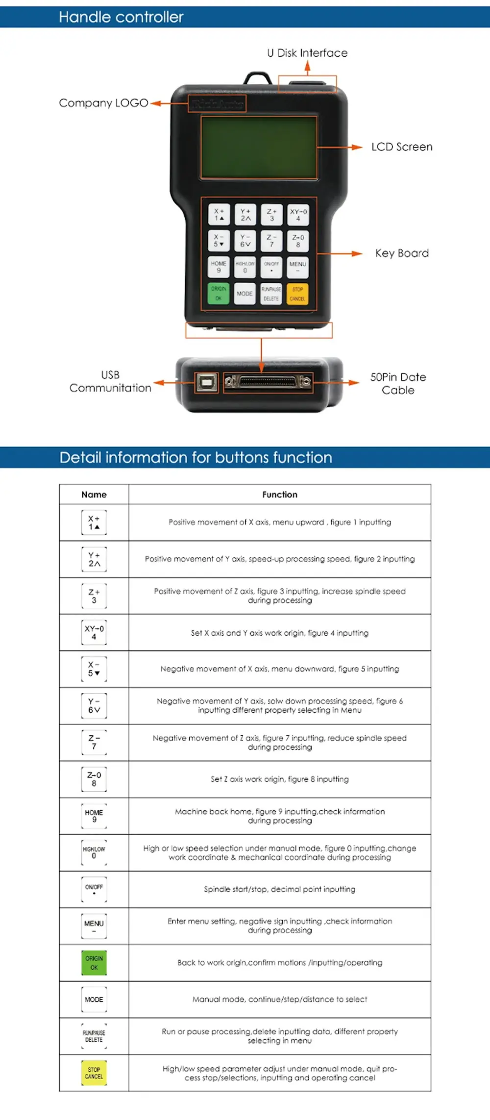
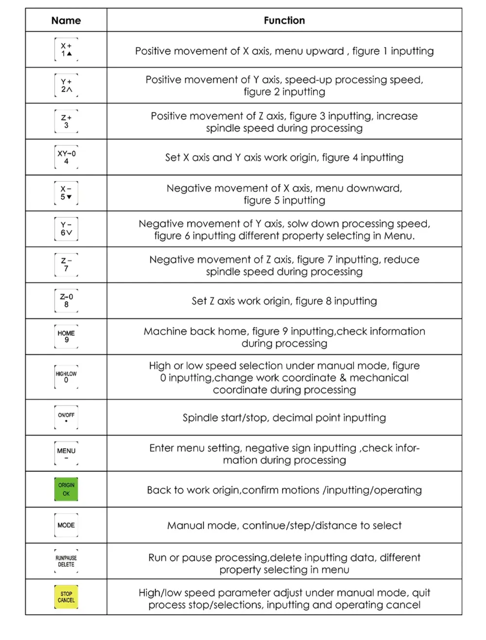
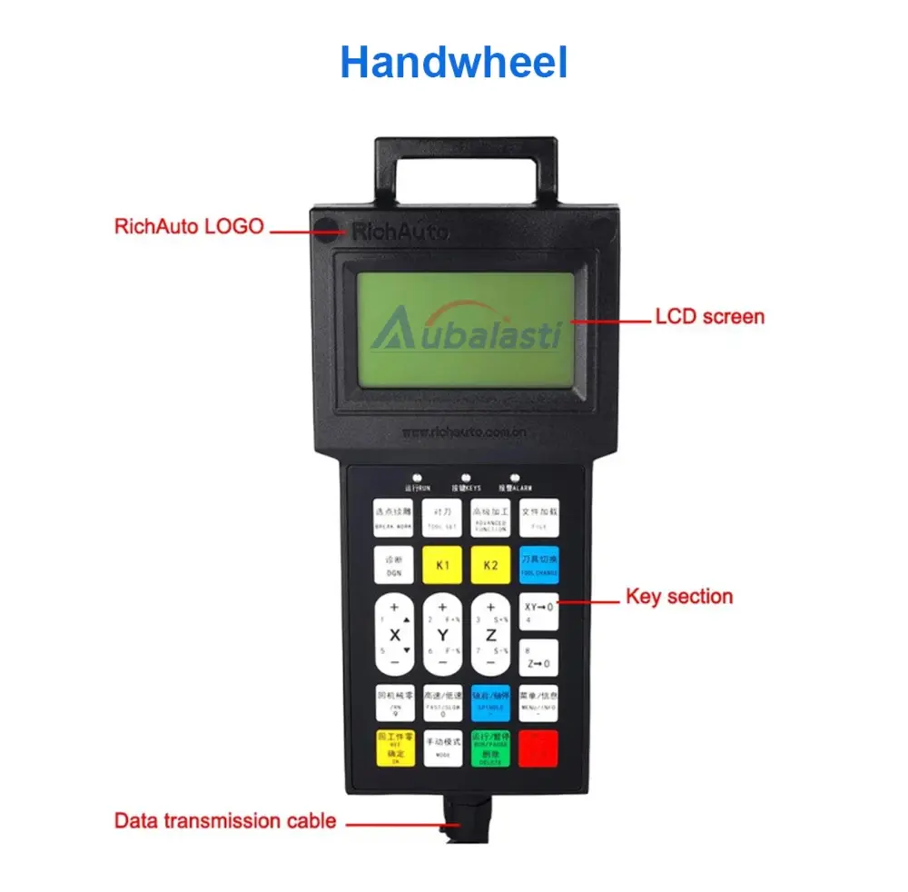
ON/OFF +XY→0 | Set XY work origin |
ON/OFF +ZC→0 | Set Z or C work origin |
MENU +ON/OFF | Automatic tool preset |
RUN +(1-8) | Breakpoint list |
RUN+HIHG/LOW | Advanced processing functions |
RUN+9 | Repeat last processing |
OK+MODE | Hold and power into U-mode |
Feature
- Adopting position control mode, support 3-axis and 4-axis linkage motion control, double Y drive.
- Standard with 8 Input/Output interface boards.
- Support various processing formats, such as G code, PLT, bitmap and DXF etc..
- Intelligent memory function, support power failure protection and breakpoint processing function.
- Support portable storage mode function.
- Multi-coordinate memory function. Proceed 9 work coordinates system, the user can switch among the 9 coordinates, each coordinate system can save a process origin information.
- Support adjusting spindle frequency during processing. The spindle frequency from 0 to maximum frequency is divided into 8 gears, 1-8 gears can be processed directly, adjusted up and down without suspend processing.
- Support adjusting speed ratio during processing. Users can adjust the speed ratio from 0.1-1, ascending or descending per 0.1 numerical.
- Simple manual operation mode. Including “Continue, Step, Dist”, manual operation becomes more simple and convenient.10. Support M, F code and other expanded codes, special code can be customized according to actual request.
- Built-in 512 Mb memory. Communication by USB interface.
- Unique handheld form to realize holding by one hand. Liquid crystal display and 16 buttons make operating intuitive and flexible. No longer dependent on the computer to realize off-line operation.
- Self-test function, system supports I/O signal detection capabilities to make remote maintenance easy.
- Support multiple languages, such as Spanish, French, Arabic, etc.
- The system supports automatically dynamic upgrading that make remote operation and remote maintenance convenient.
Port definition | Port label | Pin Definition | Pin functions
and parameters | Notes |
DC24V | 24V+ | System main power supply port | The system's main power supply terminal and interface board give DC 5V for the system. | Power area:
DC10V~DC24V/ 3A~40V |
ㅤ | 24V- | ㅤ | ㅤ | ㅤ |
X-AXIS | 5V | 5V signal output por | X-axis drive common anode power supply terminal 5V output | Do not impose voltage on this pin |
ㅤ | PULSE | Pulse signal output port | X-axis drive pulse signal output port, the output voltage ≧ 3V drive current≦ 8mA | ㅤ |
ㅤ | DIR | direction signal
output port | X-axis direction of the drive signal output port output voltage ≧ 3V drive current≦ 8mA | ㅤ |
ㅤ | SHIELD | Shield
connection port | X-axis drive signal output voltage line terminal shield | Do not impose voltage on this pin |
Y-AXIS | 5V | 5V signal output port | Y-axis drive common anode power supply terminal 5V output | Do not impose voltage on this pin |
ㅤ | PULSE | Pulse signal output port | Y-axis drive pulse signal output port, the output voltage ≧ 3V drive current≦ 8mA | ㅤ |
ㅤ | DIR | direction signal
output port | Y-axis direction of the drive signal output port output voltage ≧ 3V drive current≦ 8mA | ㅤ |
ㅤ | SHIELD | Shield
Connection port | Y-axis drive signal output voltage line terminal shield | Do not impose voltage on this pin |
Z-AXIS | 5V | 5V signal output port | Z-axis drive common anode power supply terminal 5V output | Do not impose voltage on this pin |
ㅤ | PULSE | Pulse signal output port | Z-axis drive pulse signal output port, the output voltage ≧ 3V drive current≦ 8mA | ㅤ |
ㅤ | DIR | direction signal
output port | Z-axis direction of the drive signal output port output voltage ≧ 3V drive current≦ 8mA | ㅤ |
ㅤ | SHIELD | Shield
connection port | Z-axis drive signal output voltage line terminal shield | Do not impose voltage on this pin |
Port definition | Port label | Pin Definition | Pin functions
and parameters | Notes |
OUTPUT
SIGNAL | Y01 | Y1(S0): Spindle ON/OFF | Connect to FWD of inverter | Output Low-level signal |
ㅤ | Y02 | Y2(S1):speed 1 | Connect to the inverter to control the speed | ㅤ |
ㅤ | Y03 | Y3(S2):speed 2 | Connect to the inverter to control the speed | ㅤ |
ㅤ | Y04 | Y4(S3):speed 3 | Connect to the inverter to control the speed | ㅤ |
ㅤ | Y05 | Y5(S4):Alarm LED | Light when there is something wrong with the system | ㅤ |
ㅤ | Y06 | Y6(S5):Work LED | Light when the system works | ㅤ |
ㅤ | Y07 | Y7(S6):definable | user-defined signal | ㅤ |
ㅤ | Y08 | Y8(S7):definable | user-defined signal | ㅤ |
ㅤ | GND | GND: Output GND | ㅤ | GND connects to this terminal in the control inverter speed mode |
INPUT
SIGNAL | X01 | X1:X_se:X origin sensor Signal Input | X origin sensor signal input terminal | Input low-level signals |
ㅤ | X02 | X2:Y_se:Y origin sensor
Signal Input | Y origin sensor signal input terminal | ㅤ |
ㅤ | X03 | X3:Z_se:Z origin sensor
Signal Input | Z origin sensor signal input terminal | ㅤ |
ㅤ | X04 | X4:CutterTool-setting sensor signal input | Tool-setting sensor signal input terminal | ㅤ |
ㅤ | X05 | X5:Driver alarm signal input | Driver alarm signal input terminal | ㅤ |
ㅤ | X06 | X6:Hard limit signal input | Hard Limit signal input terminal | ㅤ |
ㅤ | X07 | X7:E-stop signal input | E-stop signal input terminal | ㅤ |
ㅤ | X08 | X8:Definable signal | Definable signal input terminal | ㅤ |
ㅤ | 24V | 24V+:Sensor power input | X、Y、Z sensor isolate circuit power supply positive input terminal | Sensor isolate circuit supply voltage range DC10V~DC24V |
ㅤ | GND | GND:GDN input | X、Y、Z sensors isolate the circuit power supply negative input terminal | ㅤ |
ㅤ | SHIELD | Shield: Shield input | Sensor signal cable shield input terminal | Do not use this port as a negative use of the sensor isolation circuit power |
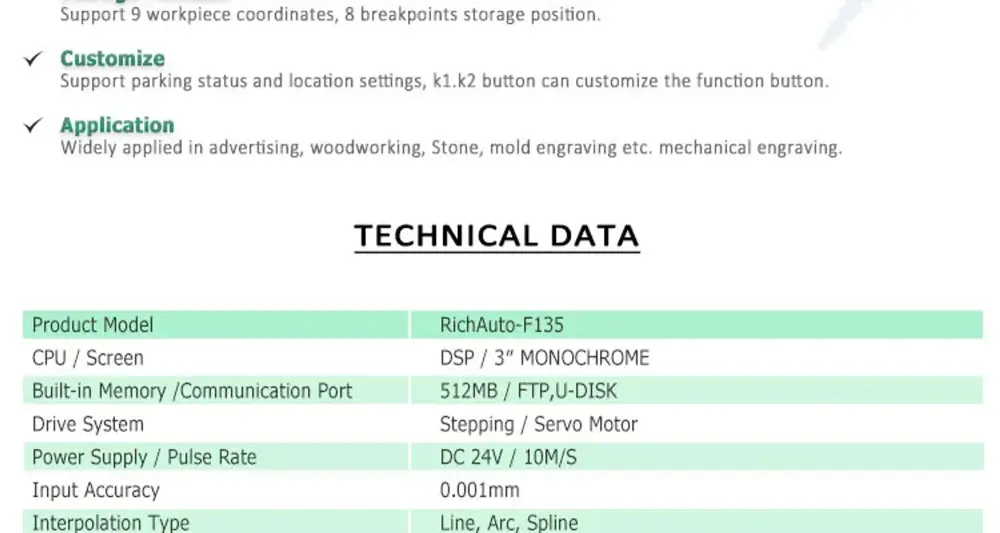
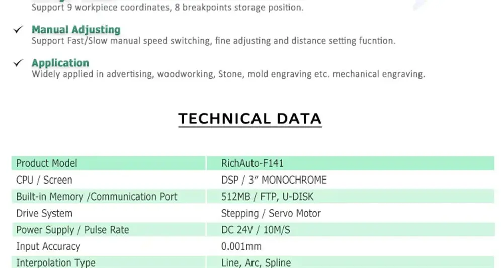
Advantage:
1. 4-axis 4-linkage motion control mode.
2. Standard 8-in 8-out IO terminal block.
3. Support 9 workpiece coordinate systems and 8 breakpoint saving positions.
4. Support floating tool setting, fixed tool setting, tool setting position, tool setting speed, etc.
5. Support rotation axis free mark (ABC optional)
6. The 4th axis can be set as a normal axis or rotary axis.
7. Support manual high/low-speed switching, fine adjustment, distance setting, and other functions.
8. Support XYZ axis driver, frequency converter, emergency stop, hard limit, and other alarm functions.
9. Support the functions of continuous carving, breakpoint saving, power-down memory, etc.
10. Support special function requirements of the array, milling plane, zoom, row selection, and automatic classification.
11. Support parking status and location setting.
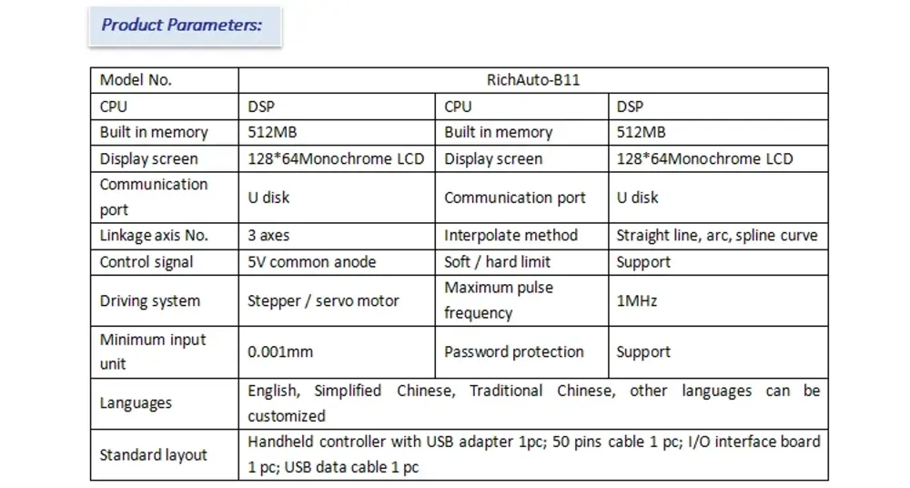
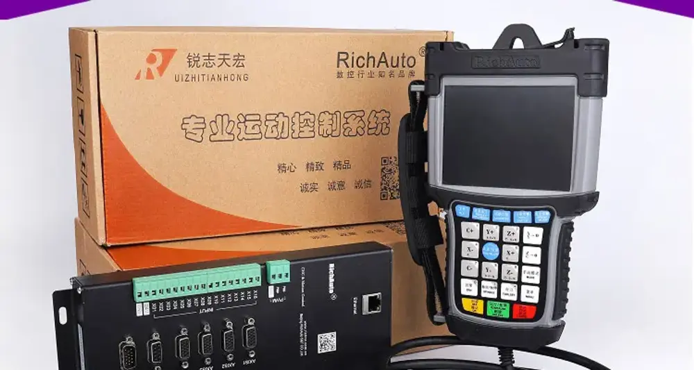
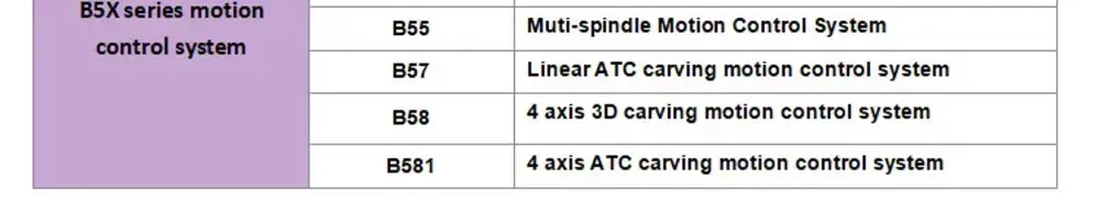
[6]DSP B15

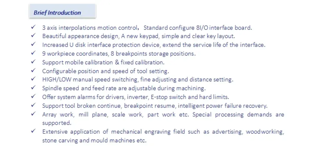
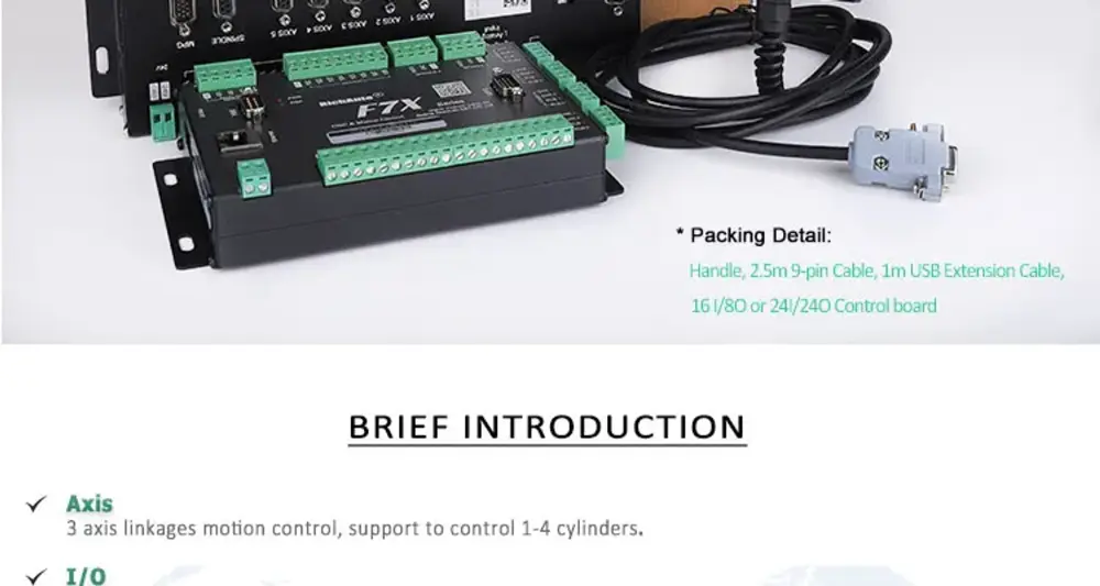
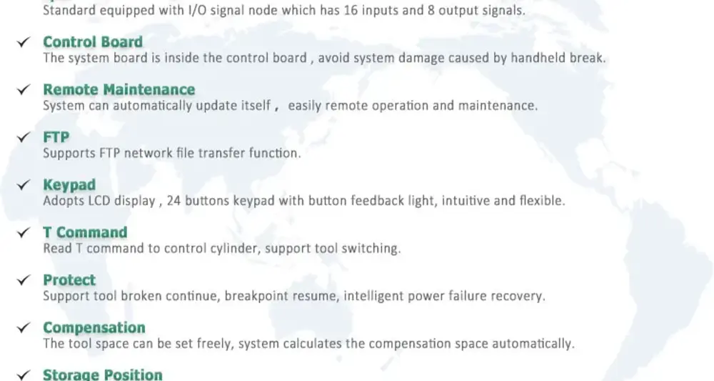
Product DescriptionRichauto DSP B15(S/T/E) Controller for CNC Router· Support 1 to 4 cylinders working, 3-axis interpolations motion control.· Customized analog IO interface board for B15 only.· Offer one tool to change the shortcut key.· Support mobile calibration & fixed calibration.· Tool setting position and speed are configurable.· Read the T command to control cylinders, spindles can switch flexibly.· Spacing between cutting tools can be set freely, and the system calculates compensation automatically.· User only needs to calibrate the cutter which is changed· 9 workpiece coordinates, 8 breakpoints storage positions.· Support tool broken continue breakpoint resume, intelligent power failure recovery.· HIGH/LOW manual speed switching, fine adjusting, and distance setting.· Offer system alarms for drivers, inverter, E-stop switch, and hard limits.· Stop position and status can be set as the user requested.
Product Parameters
Type | Data | Type | Data |
CPU | DSP | Power Supply | DC 24V 3A |
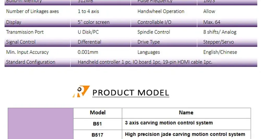
Build-in Memory | 512Mb | Pulse Frequency | 1M/S |
Display Screen | 3" Monochrome Screen | Controllable I/O | 8/8 |
File transfer | U Disk / Flash Disk Mode | Control Signal | Common Anode |
Control of Spindle | 8 multi-speed / Analog control | Input Accuracy | 0.001mm |
Number of Linkages axes | 3 axis | Drive Type | Stepper/Servo |
Language | Simplified Chinese / English / Traditional Chinese | ㅤ | ㅤ |
Standard Configuration | Handheld Controller 1 pc, 2.5m 50-pin Cable 1pc, IO board 1pc, USB cable 1 pc | ㅤ | ㅤ |
[7]DSP B18
[8]DSP B51
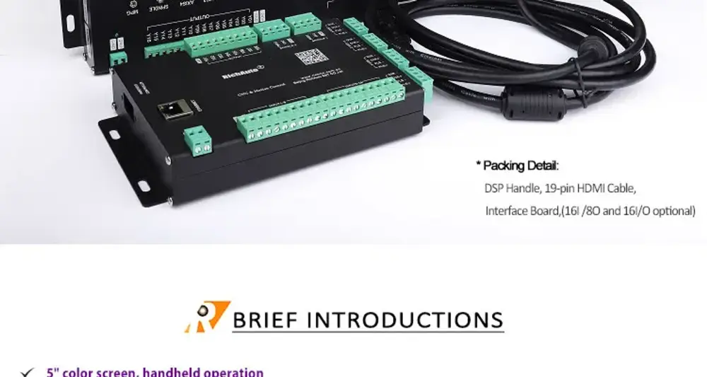
Product Description
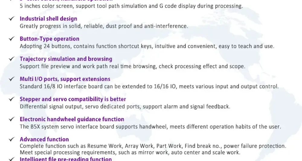
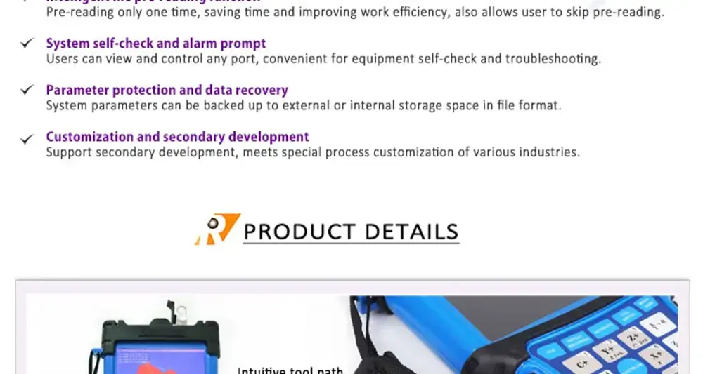
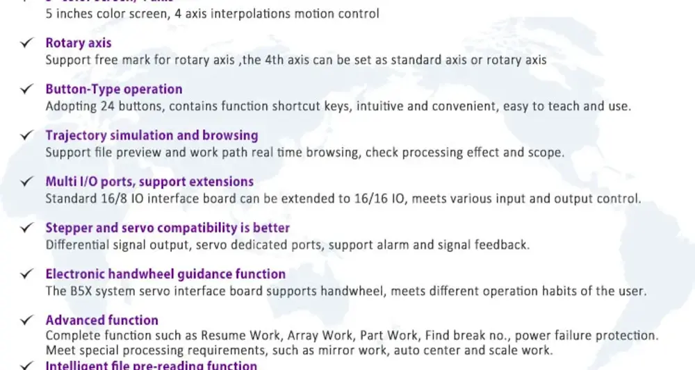
- 3 axis interpolations motion control, 5 inches color screen.
- Machining graphic simulation and dynamic display of tool path during machining.
- Display processing status, G codes, and alarm information on main screen.
- 16/8 IO interface board for stepper motor driver.
- 16/16 IO interface board for servo motor driver.
- Support network file transfer through PC upper computer program.
- 9 workpiece coordinates, 8 breakpoints storage positions.
- Support mobile calibration & fixed calibration.
- Tool setting position and speed is configurable.
- HIGH/LOW manual speed switching, fine adjusting and distance setting.
- Spindle speed and feed rate are adjustable during machining.
- Offer alarms for drivers, inverter, E-stop switch and hard limit.
- Support tool broken continue, breakpoint resume, intelligent power failure recovery.
- Array work, mill plane, scale work, part work etc.
- Stop position and status can be set as user’s requested.
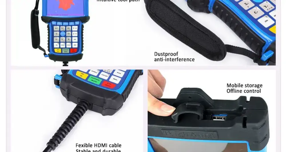
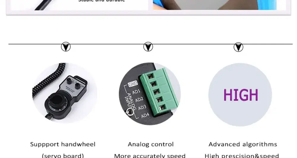
- The extending 16I/16O board supports hand wheel connecting.
- Extensive application of mechanical engraving field such as advertising, woodworking, stone carving and molded machines etc.
Technical Data
Type | Data | Type | Data |
Display: | 5 inches color screen | CPU: | DSP |
Build-in Memory: | 512MB | Power failure Protection: | Support |
Breakpoint processing function: | Support | Number of Linkages axes: | 3 axes |
Controllable I/O: | Max. 64 | Input accuracy: | 0.001mm |
Power Supply: | DC 24V/3A | Signal type: | Differential |
Max. pulse frequency: | 10MHz | Data Transmission: | U Disk, Network |
Spindle Control: | Multiple-step speed, Analog | Running Speed: | Adjustable |
Code Support: | Standard G codes, M codes, and other custom codes | Languages: | Chinese, English, and other languages can be customized |
Interpolation methods: | Line, arc, spline curve | Drive System: | Stepper/Servo |
Handwheel operation : | Optional | File reading: | NC/u00/plt/DXF/mmg |
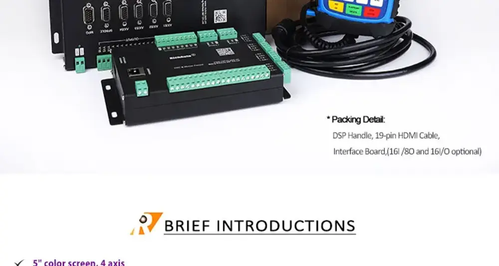
Standard layout | Handheld controller 1 pc; HDMI data transmission cable 1 pc; I/O board 1pc. | ㅤ | ㅤ |


[9]DSP B57


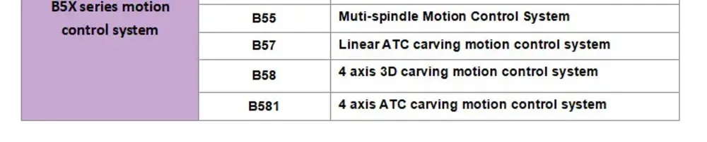
[10]DSP B58


[11]DSP F131
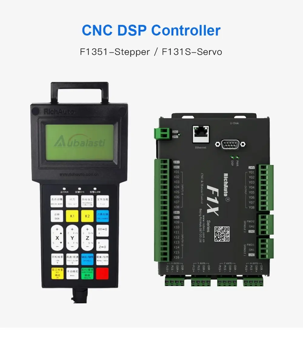
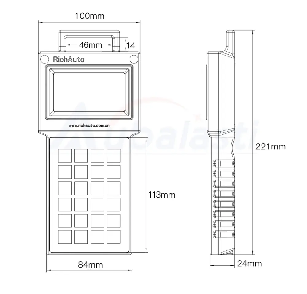
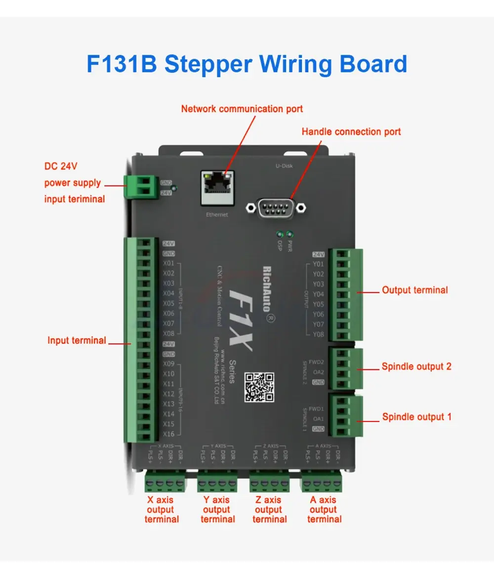
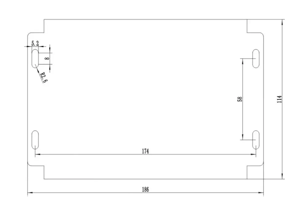
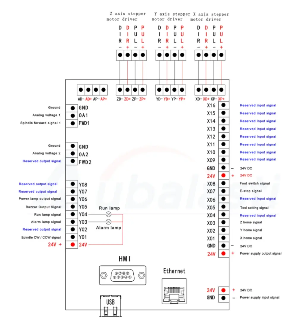
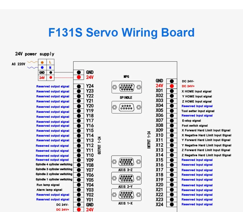
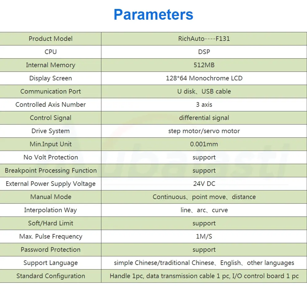
Type | Data |
product model | F131 |
drive system | step motor/ servo motor |
supply voltage | 24V DC |
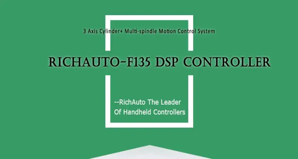
[12]DSP F135


[13]DSP F141


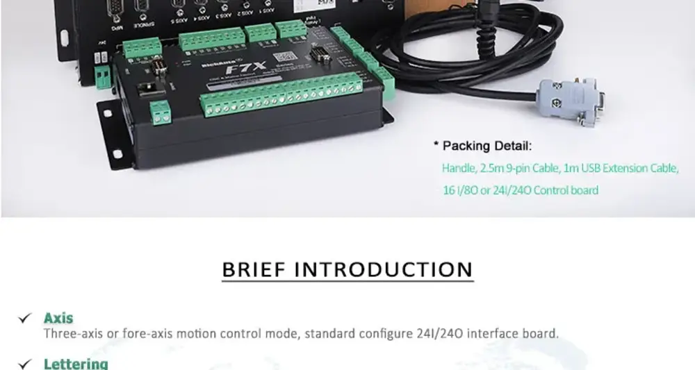
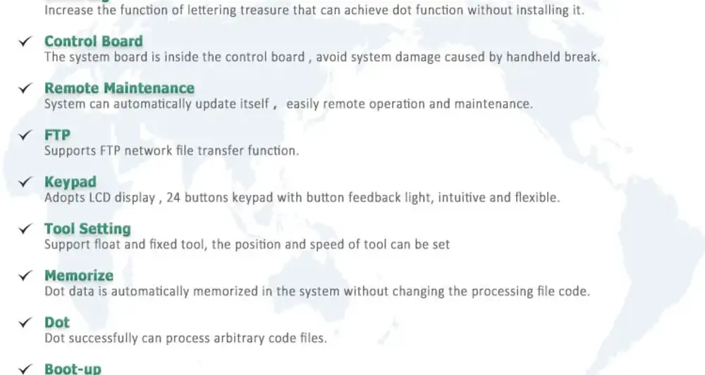
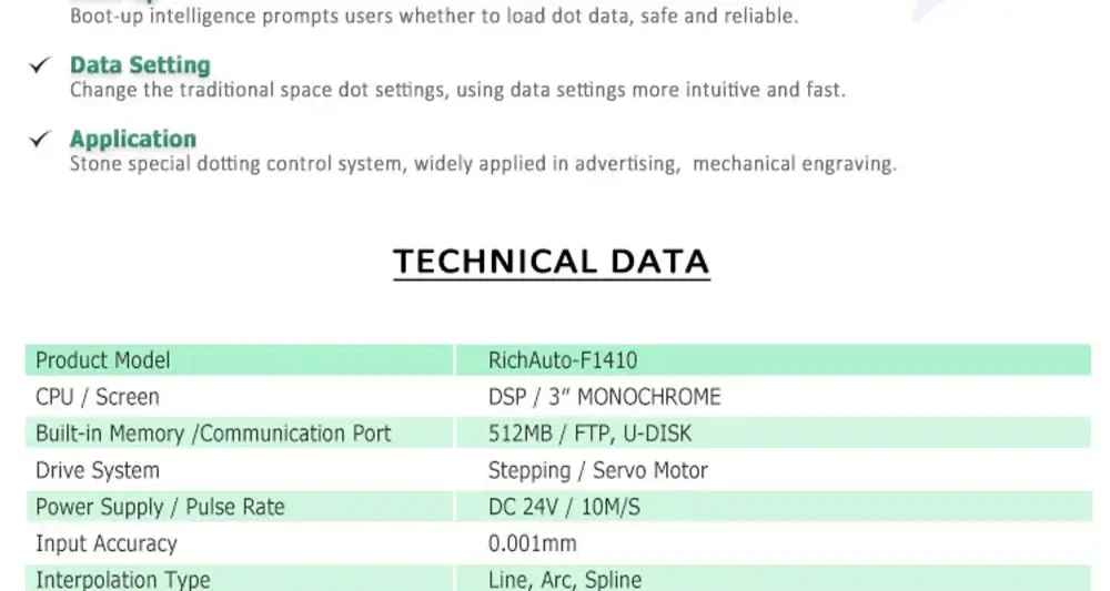
[14]DSP F1410


Last update: 2024